Description
RADYNE SFC4200 C BAND TO 70 MHz DOWN CONVERTER
RADYNE SFC4200 C BAND TO 70 MHz DOWN CONVERTER
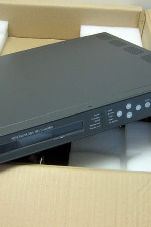
This manual discusses theRADYNE SFC4200 C BAND TO 70 MHz DOWN CONVERTER Synthesized Frequency Downconverter family of products (Figure 1-1). These include the SFC4200 C-Band, and the SFC1275G Ku-Band Synthesized Frequency Downconverters. They are high quality, rack mounted satellite Downconverters that are intended for use in medium-to-large earth station installations where multiple carrier uplinks need to be established. The SFC Downconverters are ready to be configured into a variety of backup switch configurations which include 1:1, and 1:N (to a maximum of N = 8) configurations. RADYNE SFC4200 C BAND TO 70 MHz DOWN CONVERTER
The SFC4200 Downconverter is a C-Band, 125 kHz resolution synthesized satellite
downconverter capable of converting a C-band downlink in the range of 3.620 to 4.2 GHz or
3.400 to 4.2 GHz extended band, to either a 40 MHz bandwidth 70 MHz IF output or optionally toan 80 MHz bandwidth 140 MHz carrier.
The SFC1275G Downconverter is a Ku-Band 125 KHz resolution synthesized satellite
downconverter capable of converting a Ku-Band downlink in the range of 10.95 to 12.75 GHz toeither a 40 MHz bandwidth 70 MHz IF output or optionally to an 80 MHz bandwidth 140 MHz
carrier. Gain can be controlled to 0.1 dB step resolution. Control of frequency and gain can be
accomplished through the Front Panel Controls or remotely via an RS-232 Serial Interface.
The units monitor local oscillator (LO) phase-locked loop faults in the converter at all times
during operation. If a fault is detected, the converter immediately goes into the Off Line Mode.
If multiple converters are configured to provide backup protection switching, a summary fault will signal the backup and put itself online thus restoring the failed circuit.
The RF Hardware consists of a broadband synthesizer, a fixed frequency phase locked oscillator, and the first and second converter modules. The broadband synthesizer provides the
synthesized local oscillator for the conversion from RF to L-Band. The LO that tunes from
4.6645 – 5.2425 GHz or 4.485 – 5.335 GHz (SFC4200), or from 8.88 – 10.68 GHz (SFC1275G)
performs this conversion. The second mixer converts the L-Band Signal to either the 70 or 140
MHz IF Output. A fixed frequency IFLO performs this frequency conversion.
A 40 dB gain control output attenuator at the IF controls the power out of the converter. This
attenuator is capable of 0.1 dB resolution through a software linear interpolation of 1 dB
calibration values.
The internal IF is converted by the second mixer LO to 70 or 140 MHz. The 70/140 MHz IF
chain also performs filtering and phase equalization via an all-pass network. The gain calibration process also provides gain slope across all bands to be within the specified ± 0.5 dB. Additionalgain compensation due to changes in ambient temperature provide for high gain stability overvarious operating conditions.


